Teensy Flight Controller From Scratch
Developing a flight controller based on a Teensy 3.5 and an MPU-9250 IMU
Introduction

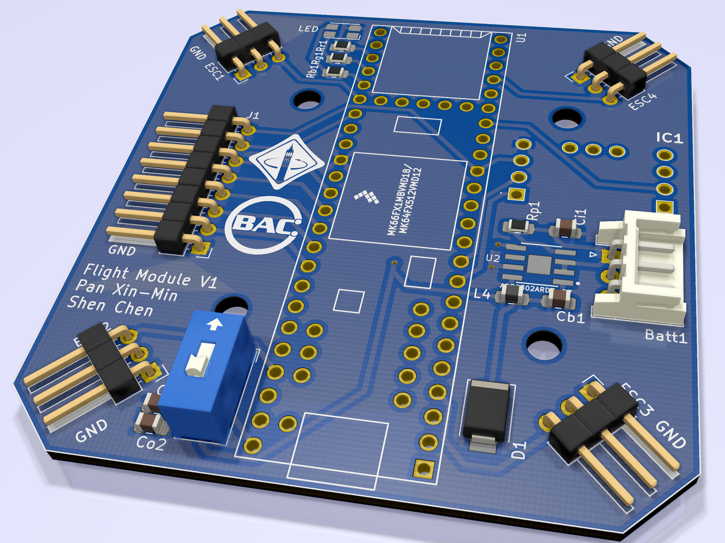
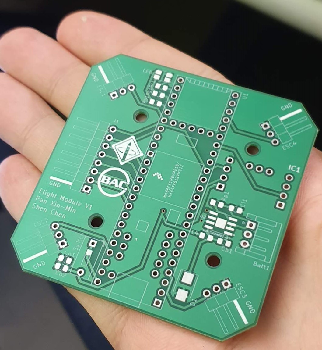
The Teensy FCFS (Flight Controller From Scratch) project came about from the UC Berkeley Hands-On PCB Engineering Decal. Students were taught to design a PCB using KiCAD along with the considerations involved in designing and assembling a PCB. This project is to create a flight controller with an Arduino-compatible Teensy 3.5, along with an MPU-9250 IMU for the sensing involved. This project also involves creating code necessary for the drone to hover and move.
Overview of Task
- Design a PCB with appropriate electrical choices (Done)
- Develop an extensible firmware for the Teensy 3.5 for controlling a quadcopter (In Progress)
Outcomes

PCB Design
Having used various Arduino boards before, the Teensy 3.5 provided a microcontroller running at 120MHz, with loads of I/O. This was thus a reasonable choice to make for the flight controller’s processor. An MPU-9250 was also selected for sensing, as the 9-DoF IMU provides loads of information that can be fused to provide accurate state estimation. This state estimation will be critical in developing a controller for stable flight of the quadcopter. An onboard multicoloured LED is used as a status light for quick debugging and flashing error codes.
From a power supply standpoint, the PCB is designed to take in power from a 2S Lithium-Polymer battery pack, providing 7.4V nominal power input. A step-down regulator, the ADP2302, is used to regulate the input voltage to 5V required by the Teensy 3.5 and the radio receiver for remote controlled flight. The Teensy then provides the required 3.3V supplies for the IMU. A switch onboard allows for the power to the Teensy to be cut for convenience and troubleshooting.
From an assembly standpoint, all components chosen are no smaller than 0806 to faciliate hand assembly via a soldering iron. The only component onboard that requires a heat gun was the ADP2302, where no alternatives were provided. This allows for simple assembly without the need for robotic pick and place machines or solder reflow ovens.
System Firmware
The firmware of the flight controller is still in progress. It’s currently being built using PlatformIO, as opposed to the Arduino IDE, which provides better support for larger, more complicated projects. Open source code from Sparkfun for the MPU-9250 is used and modified for better performance, as well as tuned for the specific magnetic field adjustments required for Berkeley, Calfornia.
As of now, the code provides barebone access to the fused orientation of the flight controller, and an arming sequence for safety. The code also provides some libraries for controlling the onboard LED, PID control and generating the PWM signals required for the ESCs. This helps to reduce the complexity of the main loop by abstracting away commonly used functions, and improves our ability to optimise the main loop for better performance with reduced processing latency.
As of now, stability control is via a PID controller, with tuned values. However, performance is not good enough for stable flight at the moment. Future updates would include experimenting with LQR control which appears to provide better performance.
Conclusion

(Pardon the poor lighting of the image, the assembled PCB can be seen in the background, the foreground shows the frame of the testing drone)
This project is a collaboration with Pan Xin-Min, my classmate from REP, and we currently have plans to continue developing this board.
While the project is still ongoing, it has taught me a great deal about PCB design. As a first-timer to this, the project has helped to bring me through the various stages of design, from drawing schematics, to trace routing. This project also helped me get familiar with KiCAD, which is a useful PCB design tool.
The firmware development will help me gain more experience with optimising code for high performance, as well as test various control strategies learnt from the UCB EE128 Feedback Control Systems module that I took. I hope to have it flying well eventually.
The code repository is accessible via my GitHub here: https://github.com/shenc909/TeensyFCFS
